В предыдущей статье упоминалось, что для подавления влияния высокочастотного шума в схему выборки тока 4-20 мА необходимо добавить RC-фильтр нижних частот перед выборкой АЦП. Используется схема RC-фильтра нижних частот, показанная на рисунке 1, где R2 равно 1,6 кОм, а C1 равно 0,1 мкФ. Тогда частота среза fc составляет приблизительно 1 кГц.
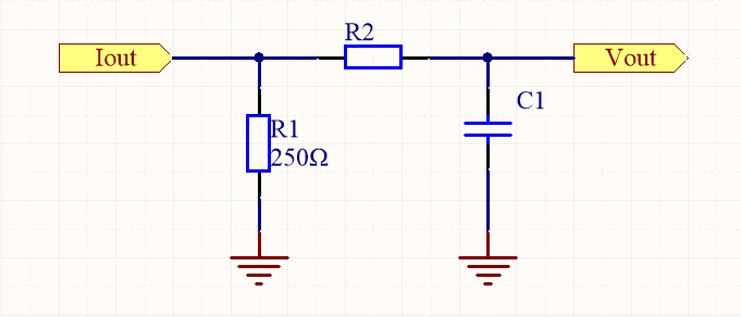
Рисунок 1. RC-фильтр нижних частот
В данном анализе рассматривается его способность подавлять шум с помощью практических расчетов, используя в качестве примеров внутриполосный сигнал частотой 200 Гц и внеполосный шумовой сигнал частотой 5 кГц для расчета его амплитудно-частотной характеристики.
Выходной сигнал типичного резисторного делителя показан на рисунке 2.

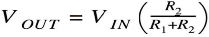
Рисунок 2. Выход резисторного делителя напряжения.
RC-фильтр использует эквивалентную структуру, заменяя R2 конденсатором. Сначала заменим R2 на емкостное сопротивление (XC) конденсатора, получив выражение для выходного сигнала RC-делителя напряжения, как показано на рисунке 3:
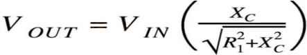
Рисунок 3. Выход резисторно-конденсаторного делителя напряжения.
Выражение для емкостного сопротивления конденсатора выглядит следующим образом:

Рисунок 4. Выражение для емкостного реактивного сопротивления конденсатора.
В приведенном выше примере проектирования R ≈ 1600 Ом и C = 100 нФ. Мы предполагаем, что амплитуда входного сигнала VIN составляет 1 В, и вычисляем амплитуду выходного сигнала VOUT, используя синусоидальную частоту 200 Гц (рисунок 5):
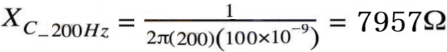
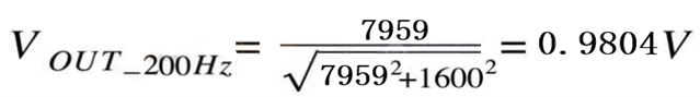
Рисунок 5
Результаты расчетов на рисунке 5 показывают, что амплитуда сигнала 200 Гц остается практически неизменной, что соответствует ожиданиям сохранения амплитуды сигнала без затухания при одновременном подавлении шума. Далее рассмотрим, как фильтр успешно подавляет шумовую составляющую 5 кГц (рисунок 6).
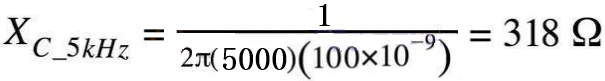
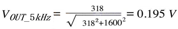 Рисунок 6
Результаты расчетов, представленные на рисунке 6, показывают, что амплитуда шума составляет всего около 20% от своего исходного значения, что демонстрирует значительный эффект подавления внеполосного шума.

Xml политика конфиденциальности блог Карта сайта
Авторские права @ Микро-Магия Инк Все права защищены.
 ПОДДЕРЖИВАЕТСЯ СЕТЬ


 русский