Схема, показанная на рисунке ниже, часто встречается в системах CAN-связи: резистор на клемме CAN не использует напрямую сопротивление 120 Ом. Вместо этого между двумя резисторами по 62 Ом добавляется заземленный конденсатор, который «разделяет» резистор на две части, что и называется методом разделения клемм.
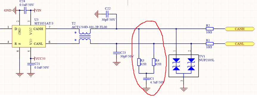
Рисунок 1. Схема интерфейса шины CAN.
Этот метод подключения на самом деле довольно сложен; он эффективно снижает внешние помехи на дифференциальном сигнале. Шина CAN передает дифференциальные сигналы, которые, как правило, обладают высокой устойчивостью к синфазным помехам. Однако для обеспечения высокой надежности шина CAN должна выдерживать различные суровые условия эксплуатации. Высокоамплитудные синфазные импульсные помехи на шине могут повредить цепь заземления внутри приемопередатчика CAN, что требует подавления помех. Самый простой и эффективный метод подавления этих помех — использование RC-фильтра нижних частот. Это включает в себя разделение оконечного резистора 120 Ом на два резистора 62 Ом, соединенных последовательно, с небольшим конденсатором, подключенным к земле между двумя резисторами. Это создает RC-фильтр нижних частот на каждом из двух дифференциальных портов передачи, CANH/CANL, на шине CAN.
Частота среза RC-фильтра нижних частот равна Fc = 1/(2πRC), следовательно, C = 1/(2πRFc). Это означает, что размер конденсатора связан с частотой среза передаваемого сигнала. Выбор конденсатора обычно определяется скоростью передачи данных. Для скорости 500 кГц мы выбираем частоту среза 500 кГц. Формула расчета емкости:
C = 1/(2πRFc) = 1/(2π*500000*62) = 5,13 нФ. Конденсатора емкостью 4,7 нФ, что близко к обычно используемому значению, достаточно.
В шине CAN используется раздельное оконечное сопротивление для более эффективной фильтрации высокочастотных синфазных помех, что повышает стабильность связи в сложных промышленных условиях.

Xml политика конфиденциальности блог Карта сайта
Авторские права @ Микро-Магия Инк Все права защищены.
 ПОДДЕРЖИВАЕТСЯ СЕТЬ


 русский